|
|
||||||
|
|
|
|
Download | |||
Diamond Version 5 User Manual: Display of structure pictureLayout
Previous article: Orientation and Position
There is an improved layout for printout pages and a layout format for fixed-sized bitmaps.
In printout page layout, you can see the entire page that will be sent to the printer. This article describes how to switch between the special layouts and normal layout and the advantages and disadvantages of the layouts. - "Bitmap layout and page layout vs. normal layout" introduces and compares the layouts.
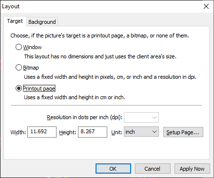
Bitmap layout and page layout vs. normal layoutAdditional to the regular way of drawing a structure picture into the structure picture pane, there are two special layouts, one to target drawing into a bitmap of well-defined width and height and a second one to draw into an area that fits with the dimensions of a printout page for printing. To switch between normal layout (called "Window" layout for disambiguation) and bitmap or printout page layout, use the Layout command from the Display menu, where you find the three options Window, Bitmap, and Printout page on the Target page of the dialog.
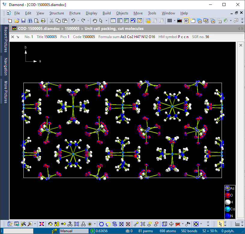
Window layout (normal layout) This is the default setting and here often simply called "normal" layout. It is generally most appropriate for creating and editing of structure pictures. The size of the drawing area is arbitrary and determined by the current with and height, in pixels, of the structure picture pane. Since the size of the application window as well as the dimensions of the several panes - structure picture pane, data sheet, tables, properties view - may vary, the structure picture uses the size that it has available for the moment. The size of the structure picture is determined by the enlargment factor (cm per Å) but it can be adjusted to fit into the drawing area, see the article "Projection". The following screenshot shows the structure picture pane for the picture "Unit cell packing, cut molecules" from the sample file "COD-1500005.diamdoc", using "Window" layout.
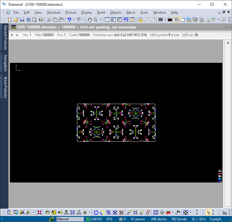
Bitmap layout With this setting, you can precisely define the size and the resolution of the bitmap on which the structure picture shall be drawn. If the size (in pixels) is larger than the drawing area on the screen, rulers will appear to its right and/or bottom. This setting is generally advantageous if you would like to create a bitmap which shall be exported to a file later on to be used in other programs (cf. the article "Saving the Structure Picture as 2D Image File"). You can adjust the Width, the Height (along with their Unit) as well as the Resolution in dots per inch separately at the bottom of the Target page of the Layout dialog. The follwoing screenshot shows the same picture as above but after switching from "window layout" to "bitmap layout" with 1920 x 1080 px at 96 dpi, leading to a width of 20 inch or 50.8 cm and a height of 11.25 inch or 28.58 cm. Since in this case the unit cell content is not automatically adjusted to the new size of the drawing area (the bitmap), there is a lot of blank space around. Coordinate system and legend are by default positioned into the top left and bottom right, rsp., corners of the drawing area. Normally this bitmap would not fit into the physical structure window pane, so there were rulers to scroll the picture inside the pane. For the screenshot we use the Scale to fit option in the Zoom dialog, so the bitmap (black background) fits automatically inside the pane (dark grey background).
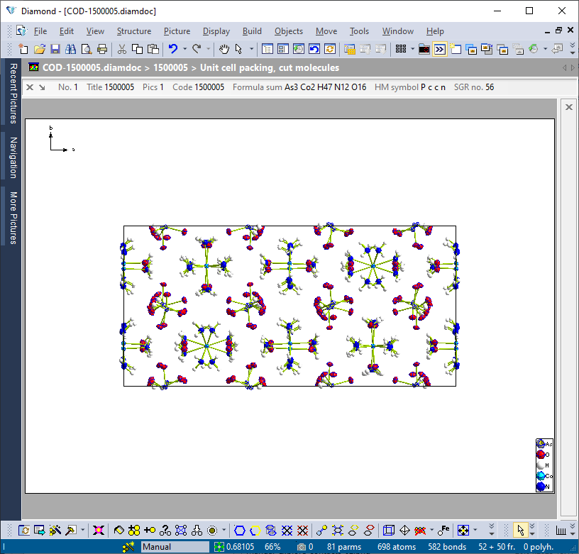
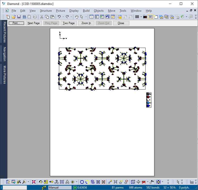
Printout page layout This setting is similar to Bitmap layout, with the exception that you define the size of the paper on which you would like to print rather than the size and resolution of a bitmap. You can adjust the Width and the Height of the paper (along with the corresponding Unit) at the bottom of the Target page of the Layout dialog. You can also use the page setup of your currently selected printer to select the paper size, simply by pressing the Setup page... button. The same structure picture as above, now in Printout page layout with an A4 page in landscape orientation. Due to the (default) setting "Use black-on-white mode for printing" on the Background page of the Layout dialog, the background color, is ignored but white is used instead. Objects with "automatic" color, which is white on dark background, turn to black for better contrast.
In summary, the following table shows differences between normal, bitmap, and printout page layout:
Page Layout vs. Print PreviewThe "printout page" layout should not be mismatched with the print preview. The print preview is a service, offered by many other Windows applications, too, that displays the active structure picture (or other graphics like diffraction diagram etc.) as it would appear when printed. It is not limited to "printout page" layout but also works for "window" and "bitmap" layout. The main difference is that in "printout page" layout the structure picture can be edited (selecting objects, rotating, etc.) like in the regular "window layout" or in "bitmap layout", whereas in print preview mode it cannot. As an example we show the Print preview of the structure picture starting from normal ("window") layout (cf. first screenshot above). Since the structure picture pane has a width and height of 792 x 592 pixels at the time when print preview is called and the default printer setting is A4 page in portrait orientation, the structure picture is fitted into the upper part of the page. A special control bar offers zooming into or zooming out of the page.
Print preview (of a structure picture) is described in the article "Printing a structure picture".
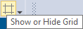
GridDiamond can display a grid in the normal ("window") layout as well as in "bitmap" and "printout page" layout, which may be helpful for the positioning of objects like text etc., to estimate the size of the structure window or printout page or to find the position of the current center of rotation in the structure picture. Note: The grid property is just auxiliary and not a property of the structure picture (like background color etc.) and thus not stored in the Diamond document (*.diamdoc). It appears only on the screen and will never be printed or written to a metafile. To enable or disable the display of the grid, push the corresponding button, which is located at the end of the Picture toolbar:
To change further settings, choose the Grid command from the View menu, which opens the Grid dialog. Defining the unit In the Unit group, you can define the unit as well as the distance between the lines of the grid. Possible units are Angstroem and centimeters. The corresponding distance values are defined in the Delta input fields. The distance depends on the current enlargement factor if defined in Angstroem. If central projection is used, this is the distance for z = 0, that means on the z level of the rotational center (with z refering to the view coordinate system). Defining the origin The Origin group defines the origin of the coordinate system of the grid. In all cases the scale points to the right and up.
ZoomIf you use "bitmap" or "printout page" layout, you can use the Zoom command to scale the bitmap canvas or page canvas, rsp. (where the structure picture is drawn) relative to the size of the structure picture pane. This command is not available (or takes no effect) in the normal ("window") layout. In the Zoom dialog, you can either select one of the pre-defined scaling sizes (given in percent), enter a Percent value on your own, or select "Scale to fit", in which case the bitmap or printout page, rsp., is scaled automatically so that it fits into your drawing area.
Double Buffering
Double buffering is a technique, where all drawings are first written into memory (into a so-called "bitmap"), and then copied fast into the structure window (screen buffer). This technique offers flicker-free display, especially when the structure is rotated or shifted in the window. To enable or disable double buffering, choose the Options command from the Tools menu, which opens the Options dialog. On the Desktop page, activate or deactivate, rsp., the checkbox Double buffering.
Some technical remarks about double buffering in Diamond
Double buffering works slightly different in flat and rendered representation:
In flat representation, Diamond stores the contents of the structure picture in a bitmap that has the dimensions of the full screen. Thus a picture need not be redrawn, if a structure window is being resized. Instead Diamond copies the bitmap centered into the structure window. If for example the screen has a resolution of 1024 x 768 pixels, and the client area of the structure window (that means the window except border, title bar, etc.) has a resolution of 600 x 400 pixels only, 212 pixels will be cut on both the left and right side of the bitmap as well as 184 pixels on both the upper and lower side, when it is copied into the window.
In rendered representation the bitmap has actually the size of the structure window's client area, which means it must be redrawn if the structure window is being resized.
If a structure window is in part or completely hidden by another application's window, it must be redrawn after that window is removed. This works quickly for both flat and rendered representation, because only the bitmap is copied into the structure window without calling the drawing function.
In flat mode, double buffering does not work if page mode has been activated, but in rendered mode it does. Please note that the bitmaps used for double buffering may occupy a lot of your computer's memory. A bitmap with a resolution of 1024 x 768 pixels and 24 bit colors ("True Color") needs about 2,359,296 bytes of memory. When you have opened multiple structure windows, this amount will be occupied for every window.
Previous article: Orientation and Position
References: |
|
Page last modified August 24, 2023. Copyright © 2023 Crystal Impact GbR. All rights reserved. Contact Webmaster |