|
|
||||||
|
|
|
|
Download | |||
Diamond Version 5 User Manual: PolyhedraPolyhedron Design and Hatching
In this article:
Previous article: Creating polygons Design and Material Properties
The design of a polyhedron face is made up of the following settings:
Since rendered representation uses neither edges nor patterns or hatching, some of the above settings will be used only in flat representation.
To define the design for new polyhedra, push the Polyhedron Design... button in the Add Polyhedra dialog or the Design... button in the Construct Polyhedron dialog.
Furthermore you can change the designs of existing polyhedra.
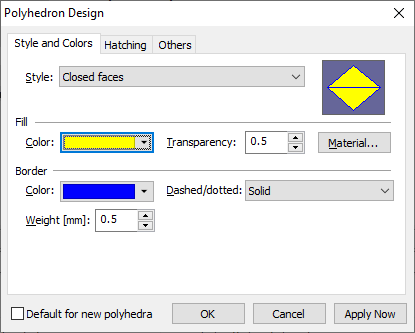
The Style and Colors page of the Polyhedron Design dialog
The design of a polyhedron is described in the following:
Style
The polyhedron style determines if the polyhedron faces are all closed, all open or partially open. The style is defined in the Style combobox.
Interior of the polyhedron faces
Like for atoms or thick bonds, you can define a color and a brush for the interior of the polyhedron faces.
Furthermore you can assign the central atom's main color, if you check the Use central atom's main color as interior color checkbox (which makes the individual color not unavailable).
The main color is derived from the central atom's design:
The main color is the interior color of an atom If the atom is hollow or has black or white as interior color, Diamond takes the edge color instead.
If you do not use the central atom's main color, you can select a color from the color select box Color.
The brush can be selected from the Brush combo box:
Edge of the polyhedron faces
You may define an edge for the polyhedron faces or not. The thickness of the edge is defined in millimeters in the Thickness input field. The color is selected from the Color select box in the Edge group. The pen can be selected from the combo box Pen:
Material properties
The Material button opens the Materials Settings dialog and offers you several material properties for the rendered representation of polyhedron faces.
In principle these settings behave like for atoms and thick bonds;
compare the article "Material Properties".
Material properties take no effect for flat representation.
Hatching
In flat representation mode, you can use real 3D hatching for the polyhedron faces. Unlike the pre-defined MS Windows hatched brushes, this kind of hatching is done by drawing 3D lines across the polyhedron faces. These hatching lines are oriented against a hatching vector to define the preferred orientation of the hatching lines to be parallel with the polygon edges.
Hatching is not used in rendered representation mode.
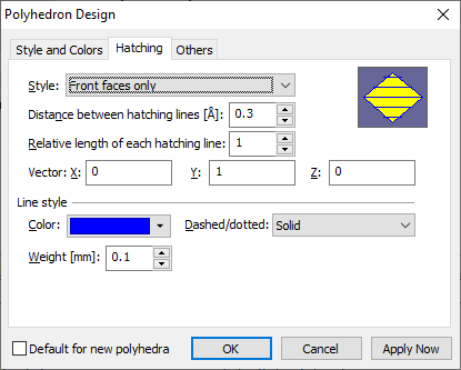
Hatching is defined on the Hatching page of the Polyhedron Design dialog.
Selecting hatching
The combo box Style defines if and what faces are to be hatched. You may choose one of the following settings:
Orientation of hatching
For each polyhedron face (polygon), the hatching lines are parallel to one of the polygon's edges.
When Diamond selects this edge, it uses that edge that is at most vertical with the "hatching vector".
The three components of the hatching vector are defined in the input fields Vector, X...
The three components of the vector refer to the reference coordinate system.
The distance between the (parallel) hatching lines is given in Angstroems in the input field Distance. When you change the enlargement factor the distance increases and decreases with the corresponding amount.
Relative length for each hatching line
If this value in the input field Relative length... is 1 (default value), the hatching lines touch the polyhedron edges. With a value between 1 and 0 these lines will be drawn shorter. E.g. with a value of 0.8, 10 percent at each end of the line will be omitted. This option may be used to contrast with the polyhedron edges.
Style, color, and thickness of the hatching lines
The color of the hatching lines is defined by the color select box Color,
whereas the combo box Pen defines, if and how lines will be drawn.
The input field Width defines the thickness of solid hatching lines in millimeters.
Please note that "dashed" and "dotted" lines will use only one pixel of thickness, regardless what is defined in Width.
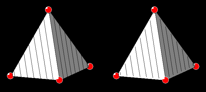
Two illustrations of a Si-O tetrahedron in alpha-quartz. Both with a hatching distance of 0.3 Angstroems. The left picture uses the default value for the "Relative length of each hatching line" of 1.0, the right one a value of 0.95, so that the hatching lines do not touch the polygon edges.
Displaying Polyhedra With Front Faces Open
Since you must select polyhedra via the associated central atom, you may get problems when you use of polyhedra with closed faces (the regular case).
It may be difficult and tedious to match the invisible central atom for selecting.
To avoid this, Diamond offers a function that hides temporarily all front faces of all polyhedra.
Please note that this does not change the polyhedron style from close faces to front faces open, and this property will not be saved with the Diamond Structure Document.
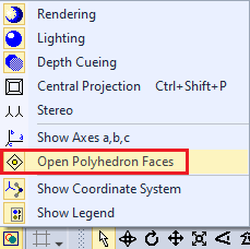
When all front faces have been opened, you can easily access the polyhedra's central atoms. To open polyhedron faces temporarily, push the Picture Settings button in the Picture toolbar and choose the Open Polyhedron Faces command:
Or choose the Hide command from the Display menu, and check the Hide front faces of all polyhedra checkbox in the Hide dialog.
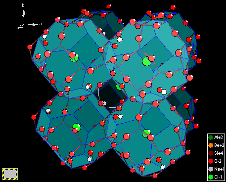
The Sodalite example with temporarily open polyhedron faces.
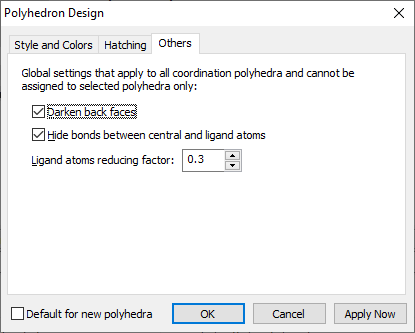
Global Settings For All PolyhedraWhile most of the settings can be defined individually for each coordination polyhedron, some settings apply globally to all polyhedra. To change these settings, go to the Others page of the Polyhedron Design dialog.
These settings are:
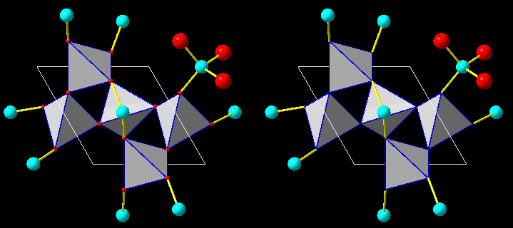
The structure of alpha-quartz, both using Si-O tetrahedra. The left picture uses a ligand atoms reducing factor of 0.3, the right one a factor of zero, which means that no ligand atoms are drawn.
Previous article: Creating polygons |
|
Page last modified September 15, 2022. Copyright © 2022 Crystal Impact GbR. All rights reserved. Contact Webmaster |