
|
|
||||||
|
|
|
|
Download | |||
Diamond Version 5 User Manual: Building up structural partsCell Edges
This chapter tells you how to: - add the edges of the unit cell or of an arbitrary cell range to the structure picture, - design the cell edges, - destroy cell edges. Furthermore, you can switch on or off the display of the unit cell base vectors a, b, and c. See the article Unit cell vectors a, b, c, and atom vectors.
Previous article: Filling cell ranges Adding Cell EdgesCell edges can be added to the structure picture either automatically or manually. Some of the functions that build up a structure picture make use of an option, which automatically generates the cell edges within the cell range, where atoms are to be generated. The simplest case: If you generate the contents of the unit cell, the unit cell edges may be added automatically. For more information, how cell edges can be added automatically, see the article "Filling cell ranges".
To add the edges of the unit cell manually, using the default design (see below),
either push the To add the edges of the unit cell and change the default design or add edges of an arbitrary cell range, choose the Add Cell Edges command from the Build menu, which opens the Add Cell Edges dialog. Define the six border values for the cell range (the default is XMin = YMin = ZMin = 0 and XMax = YMax = ZMax = 1, which defines the unit cell edges), adjust the style settings in the Style for new cell edges group, if necessary, and then push the OK button. This will generate the cell edges. Existing cell edges will not be overwritten. The latest cell edge design will be saved as default cell edge design in the Diamond section of the Windows registry, when you close the dialog box. More information about cell edge design is given below.
Designing Cell EdgesTo change the default design for cell edges or to update the designs of existing cell edges, choose the Cell Edges Design command from the Display menu, which opens the Cell Edges Design dialog. Select the color for the cell edges from the Color color select box, the pen from the Line style combobox, and define the thickness in millimeters in the input field Weight. The pen can be selected between solid (which is the default), dotted or dashed lines. The line width is applied only for the solid pen. Please note that the pens "dotted" and "dashed" use a MS Windows line pattern that depends on the resolution of the target device. That means the dots appear denser and the "dashes" shorter on a printer with high resolution than on the screen. If you define a thickness of zero, Diamond uses a pen that is only one pixel thick. Unlike (thick) bonds, cell edges cannot be displayed as cylinders, and thus not be tapered. When using rendered representation, thick cell edges will be displayed as cylinders instead of lines only, and will thus be shaded like thick bonds.
The latest cell edge design will be saved as default cell edge design in the Diamond section of the Windows registry, when you close the dialog box.
Removing Cell Edges
To delete all existing cell edges from the structure picture, choose the All Cell Edges command from the Destroy submenu of the Build menu. This will destroy all existing cell edges. If you want to destroy only a part of the cell edges, you must first destroy all, and then re-build the desired cell edges. Read the article Destroying all or parts of the structure picture about additional options what to delete (or hide) when you run the commands "Destroy all" and "Destroy cell edges" from the "Build/Destroy" sub-menu.
Previous article: Filling cell ranges
|
|
Page last modified July 12, 2022. Copyright © 2022 Crystal Impact GbR. All rights reserved. Contact Webmaster |
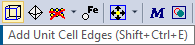 button in the Build toolbar,
or use the "hotkey" Shift+Ctrl+E.
button in the Build toolbar,
or use the "hotkey" Shift+Ctrl+E.