|
|
||||||
|
|
|
|
Download | |||
Diamond Version 5 User Manual: Display of structure pictureOther Effects
Previous article: Lighting
This article informs about further settings that can be defined for a structure picture:
· Depth cueing makes objects brighter or darker dependent from the object's "depth",
i.e. the z-value (in view coordinates).
· The shading edge is an edge
(additionally to the edge that is mostly used for an atom or bond) around each atom and bond and is used to bring them out from other objects in the rear.
· Front emphasizing is used
to enlarge the width of the edges of atoms, bond tubes, polyhedra etc. This value is added to the generic width of the edges.
The front emphasizing value refers to the most front object of the picture and is interpolated for all objects with z > 0 between 0 and this value.
The edges of objects with z < 0 leave unchanged.
· Bond tapering distorts
thick bonds, which are displayed as tubes, for a better impression of depth. Finally, there is a note about the formerly used overall radius factor, a factor all atomic radii were multiplied with.
Depth Cueing
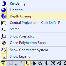
Depth cueing is an effect that makes objects brighter or darker dependent from the object's "depth", that means the actual distance from the viewer. Normally objects in the rear become darker, but you have the possibility to reverse this effect by defining a negative value for the depth cueing intensity. You can switch depth cueing on or off, simply by pushing the Picture Settings button in the Picture toolbar and choosing the Depth cueing command from the popup menu:
To enable or disable depth cueing and to define its intensity, choose the Picture Settings command from the Display menu, which opens the Picture Settings dialog.
You will find the settings on the Representation page in the Depth cueing group.
To enable depth cueing, check the checkbox enabled. To define the intensity of depth cueing, edit the value in the Intensity input field. The intensity is defined in RGB units per Angstroem. That means, an object is 10 units per color component (red, green, blue) darker, if its z-value of the view coordinates is 1 Angstroem smaller than an object, which is 1 Angstroem nearer. The depth values are relative to the current center of rotation, so that objects with z = 0 keep their original brightness. In rendered representation, unlike in flat representation, objects in the front will not become brighter. The range for each color component is 0 (no intensity) through 255 (maximum intensity). The depth cueing effect is the stronger the higher the absolute intensity value is. A negative sign inverts the effect, that means objects in the rear become brighter, instead of darker. Inverted depth cueing gives good result for colored printouts on white background, since the objects in the rear seem to vanish in the haze.
Shading Edge
Shading edges can be drawn around atoms and bonds to bring them out from other objects in the rear. This kind of edge is different from the edge that may be defined for atoms and thick bonds.
The shading edge is only used in flat representation.
To edit the line thickness of the shading edge, choose the Picture Settings command from the Display menu, which opens the Picture Settings dialog.
On the Representation page, edit the value in the input field Shading edge.
If you do not want any shading edges, enter a value of zero. Otherwise enter the line thickness in millimeters.
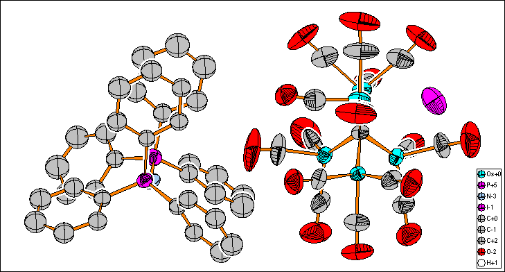
The use of shading edges decreases the drawing speed, since shading edges and their associated objects must be drawn separately. The shading edge will only "separate" objects from those in the rear but not be used for interpenetrating atoms and bonds. That means there is no shading edge between an atom and bonds leaving the atom into the viewer's direction. The following picture will illustrate the usage of shading edges (here it has a thickness of 1 millimeter):
Reference:
Name
Front Emphasizing
Front emphasizing means that the edges of atoms, bond tubes, polyhedra etc. in the front are thicker than those in the central or rear part of the structure picture. This is the method of choice if you want to enhance the 3D impression on a pure black-and-white printout, where you cannot use depth cueing.
Since there are no edges in rendered representation, front emphasizing is only used for flat representation.
Diamond uses a value which is added to the generic width of the edges in the front. The front emphasizing value refers to the most front object of the picture and is interpolated for all objects with z > 0 between 0 and this value. The edges of objects with z < 0 leave unchanged.
To edit the front emphasizing value, choose the Picture Settings command from the Display menu, which opens the Picture Settings dialog.
On the Representation page, edit the value in the input field Front emphasizing. The value has the dimension millimeter.
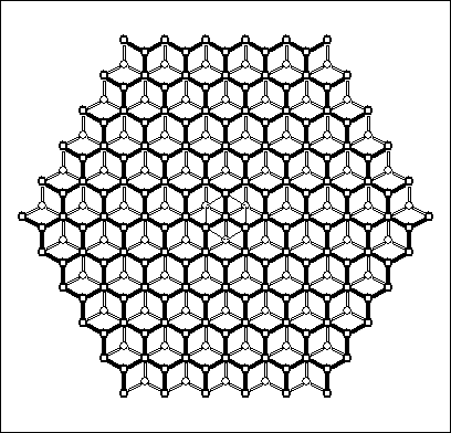
The following picture shows the effect of front emphasizing for two layers of graphite:
Bond Tapering
Bond tapering is an effect that distorts thick bonds from tubes to tapers or cones to enhance the 3D impression of the structure picture. The front end of each bond has the thicker end of the taper, the rear end has the thin end or - in extreme cases - the peak of the cone.
Bond tapering is used for both flat and rendered representation.
To edit the bond tapering factor, choose the Picture Settings command from the Display menu, which opens the Picture Settings dialog.
On the Representation page, edit the value in the input field Bond tapering factor.
For a value greater than 0, cylindric tubes are distorted to tapers with the thicker end in the front.
In the extreme case, i.e. the tube is parallel to the z-axis and the bond tapering factor is 1 (or higher), the taper becomes a cone.
Tapering factors higher than 1 may be used to distort even bonds at acute angles to the drawing area to cones.
Negative values would invert the effect, leading to thicker ends in the rear and thin ends in the front.
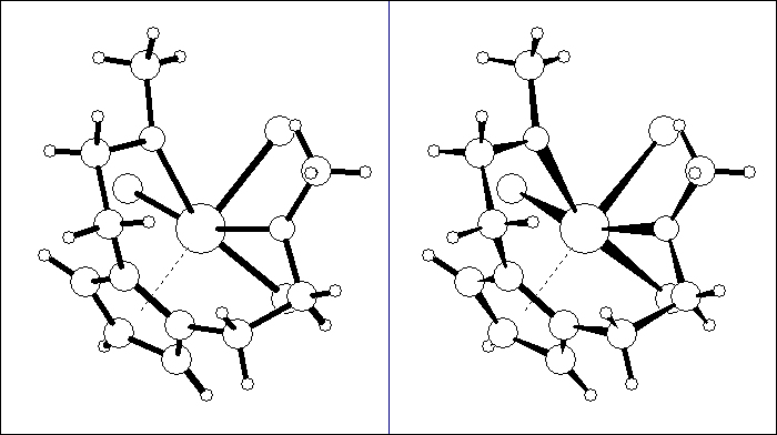
The following illustration displays a molecule of [1,2-Di(methoxyethyl)cyclopentadienyl]-trichlorozirconium(IV), in the left half with a bond tapering factor of zero, in the right half with a factor of one.
Overall Radius FactorThe overall radius factor was originally introduced as a general multiplier for atoms to be displayed in the ball-and-stick model. This value is one by default, but could be changed to increase (> 1) or decrease (< 1) the radii of the atoms globally. This overall radius factor is not more available since version 4 of Diamond. Instead you should use the Model and Radii dialog, available from the Display menu, to multiply all (or the selected) atoms with a radius factor. See the article "Models" how to do this. The advantage is that after multiplication of the actual drawing radii it easier and more transparent to check and edit the radius values rather than being irritated because the radius in the Atom Design dialog does not correspond with the radius used in the structure picture, because there is somewhere else defined another (global) radius factor.
Previous article: Lighting |
|
Page last modified September 20, 2022. Copyright © 2022 Crystal Impact GbR. All rights reserved. Contact Webmaster |